The Input Port Access Pad
The Input Port Access Pad is used to connect wires to the input ports on a module. These arrive from the output ports of other modules in the map. Clicking the right-hand mouse button on the input port access pad (the button on the left-hand side of the module control panel below the title bar) causes a menu to appear showing the possible connections that can be made and some information about them. An example is shown below. Notice that both the Transform and Colormap inputs are shown as optional.
Figure 7.1: The LatToGeom module with the input port access pad selected
Each port accepts only the data type indicated on the menu. A module requires data on all input ports (except those marked as optional) before executing (known as firing). The module automatically fires as soon as the required connections are made or when the data on the port changes (unless the module is disabled). Firing can also be forced via a connection to the Fire port (see The Output Port Access Pad below).
The Output Port Access Pad
Similar to the input port access pad, the Output Port Access Pad is used to connect output data to the input port of another module. Clicking the right-hand mouse button on the output port access pad (the button on the right-hand side of the module control panel below the title bar) causes a menu to appear showing the possible connections that can be made and some information about them. An example is shown below.
Each port outputs only the data type indicated on the menu. Data appears on the Firing Done port when module has finished executing. This can then be passed to another module's Fire port to force them to fire serially without any other new data being passed to the downstream module.
Figure 7.2: The LatToGeom module with the output port access pad selected
Connecting Modules Together
- Bring up the output menu of the first module, and choose an appropriate output port.
- The selected output port access pad is highlighted in dark green. Note that compatible input port access pads are highlighted in a lighter green.
- Bring up the input menu for one of the highlighted input port access pads, and select an appropriate input port. You can cancel the connection before selecting the second port by clicking the left-hand mouse button on the background of the Map Editor.
- The highlights disappear and a wire appears connecting the modules.
Connecting modules together is simply a matter of selecting an output port to connect and then choosing a compatible input port on another (or even the same!) module. To approach this step-by-step:
Alternatively, the connection can be created in the opposite direction (input to output) in the same way.
Disconnecting Modules
Once a connection has been made, the port menu shows the name of the other module and its port name in a cascading menu. To break the connection, select this name on the menu. The number preceding the entrance to the cascading menu shows how many connections this port currently has (as it can have more than one).
Figure 7.3: Breaking the connection between the ReadPheonics and ChannelSelect modules
Connecting Multiple Inputs/Outputs to a Port (Fan-in/Fan-out)
An output port can be connected to more than one input port (which could be on the same module, or different ones). Each input port receives the same output. This is called fan-out. An input port can be connected to more than one output port (which could be on the same module, or different ones). Some input ports use all the outputs from connected modules (fan-in), others use just the latest connection.
To add a connection to a port, proceed with the connection as normal using the <CONNECT> bar on any ports with an existing connection.
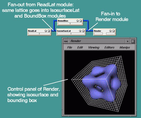
Figure 7.4: An map using Fan-in and Fan-out
Previous : Index : Next © The Numerical Algorithms Group Ltd. Oxford, UK. 1999